
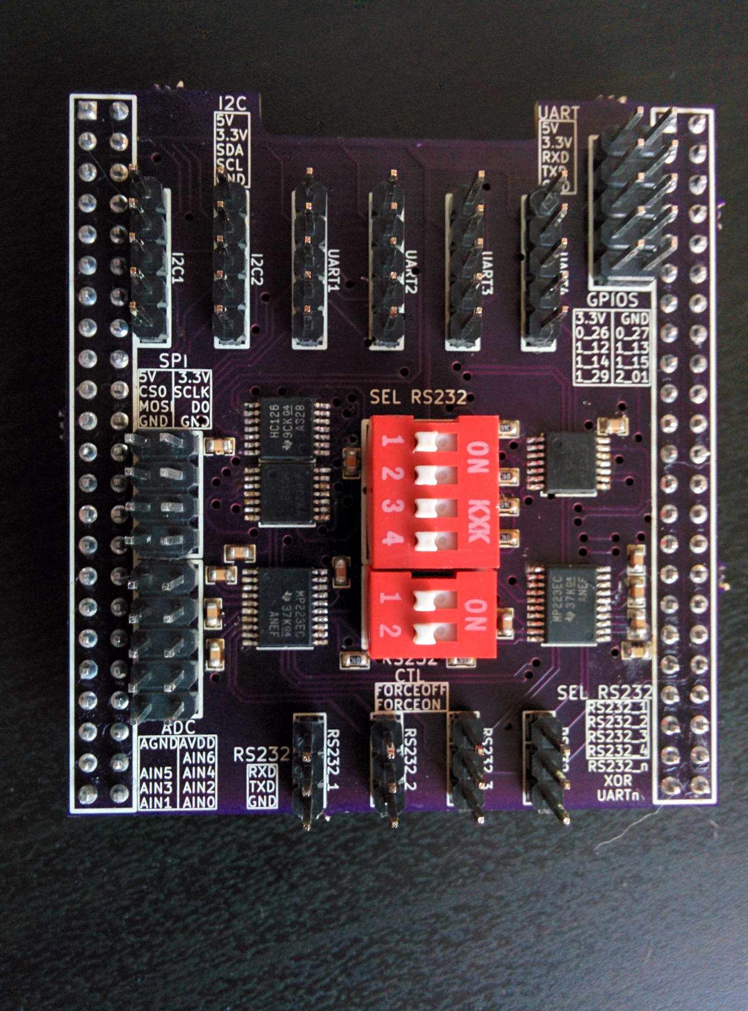
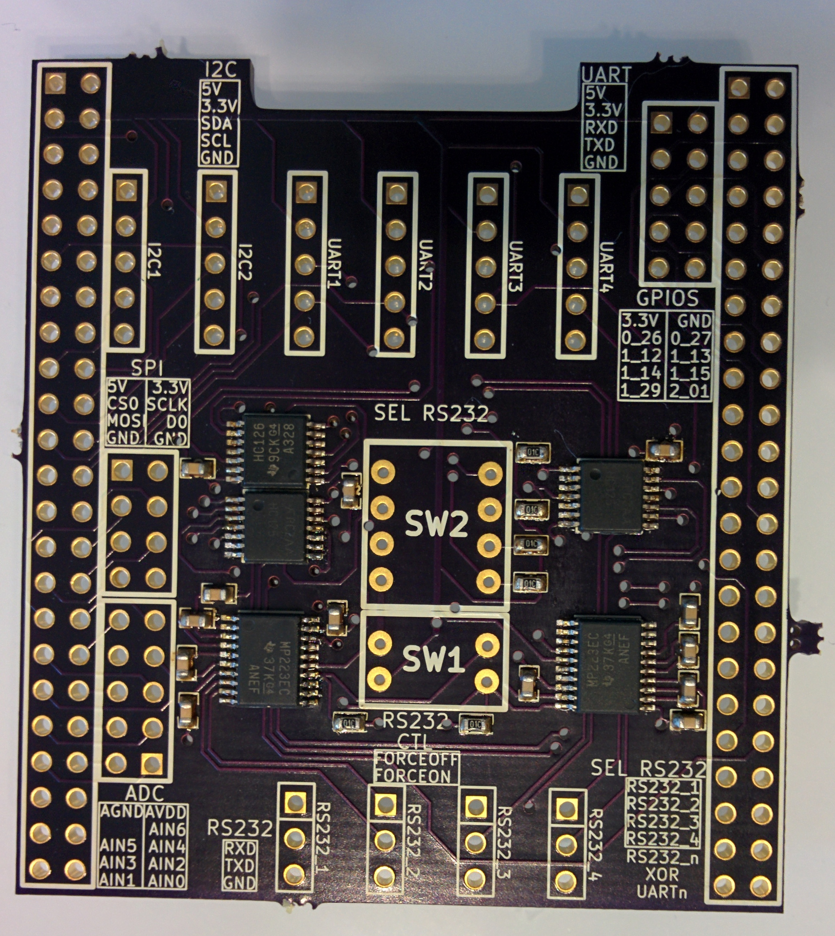
BeagleBone Black Cape (UART/RS232)
There are many capes and documentation for the BeagleBone black out there. However the most annoying thing when using the BeagleBone were always the terribly designed pin headers which are simply not meant to be used for temporary connections with different components like I2C stuff. It is not convenient to have to look the pins up before connecting.
So as I was interested in how PCB design works etc. I simply designed a cape for exactly this purpose, as a much easier way to connect to the essential pins of BeagleBone. To be also able to use this as a remote console for other embedded boards, I added some converters for 3.3V level UART to RS232.
At the end, this cape contains 2 I2C pin headers, 1 SPI, 8 GPIOs, 4 UART, 4 RS232 (although these can only be used when the correspending UART is disabled via a switch). Most pin headers contain additional power pins, 3.3V and/or 5V.
Design
To design this PCB I used KiCad which is an open source toolchain for PCB design. I never used any other PCB software before but it was quite clear how to use it after reading a bit of the documentation. I used explicitly small SMD components to find out how to reflow solder components.
Download
Here are all the files of the design:
I directly uploaded the revision 1 gerber files to oshpark. All fotos you can see are with the pcbs from oshpark. Soldering
The SMD components that I used for this board are probably for many people still within the range of handsoldering. However, as I wanted to learn something new with this project, I tried to do it with solder paste and a ‘reflow oven’. It sometimes sounds quite difficult to do it but it is actually very easy.
If you have, you can use a solderpaste mask for your board, which makes the right placement of solderpaste even easier. But it is also possible with a solder paste syringe. After putting a little bit of solder paste on every SMD pad you put the component into the solder paste. For SMD ICs you can simply put a small line of solder paste across all pads. You don’t have to align the components extremely accurate as they all will straighten up when the solder gets liquid.
I reflowed all three boards that I have and gained some feeling how much solder paste is necessary for the pads. Essentially you can’t do much wrong as you always have the option to resolder components after they were reflow soldered. I had to do that with nearly all the ICs because there were some solder brigdes between pins. But that still was quite easy and fast done. However next time I will use a stencil for the solder paste as I recently discovered oshstencils.
For reflowing you don’t need some expensive reflow oven, any oven will do. The only thing you should have is a thermometer which you can put into the oven to observe the temperature.
Software
As you have to support this hardware from Linux somehow, I wrote a devicetree patch for the am335x-bone-common file, although I am not sure if this cape really will work for the beaglebone white. I tested the UART ports, I2C and SPI are still missing as I didn’t have a i2c/spi device. However if you run into problems let me know. The patch is currently based on 3.16-rc.
Of course this is all ‘as is’, no warranty. Everything you can see is open source. The hardware design is open hardware, so feel free to modify it. However it would be great to hear about any modifications or experiences, feel free to contact me.